
Tagged: DIY (Do-It-Yourself)
My DIY Boom Box doing time with AC adapter and hanging bed switch
I got lots of speakers, media players and amplifiers. I have two amplifiers in development. So, I moved my original LM386 DIY Boom Box to the kitchen where it is powered by a AC adapter. To cut the power when not in use, I have added a hanging bell switch. I had to slice the cable to add the switch. As I could not find a stand for the entire thing, I built a nylon fibre rope hammock for it.

DIY RJ45 plug locking tab protector made from cable sheath
With great hope, I cut a piece of the sheath and stuck it to the RJ-45 plug (I crimped a new one today) just below the locking tab, taking inspiration from the Sugru RJ-45 protector on Instructables.com. I don’t know where to get Sugru from. When I tried to plug it in, I realized that the LAN port on my laptop is upside down making the access to the locking tab extremely difficult. For other laptops, this sort of protection could be useful. If you use Wi-Fi, you are an idiot.

Adding MORE POWER to puny speakers
A recurring theme in Tim Allen’s show-in-a-show Tool Time (Home Improvement) was MORE POWER. Tim Allen used to take regular devices and boost them up with more high-rated components. My last two DIY projects are like that.
A website was selling a portable USB speaker at a discounted price of Rs. 53. (The delivered piece does not look like the photo on the website.) I was not successful in applying the discount but a co-worker managed to do so. However, he was disappointed to find that that it used a puny speaker with almost no power in its output. I replaced the original speaker with a regular better-rated one. The circuit board uses a PAM 8002 speaker amplifier IC. It is originally meant for cell phone speakers but it is able to drive this speaker as well, but not as great as the PAM 8403.


A low-cost DIY desktop USB speaker
This plastic bottle came as a “free” item with a Horlicks pack. I put a speaker on top of it and harnessed it with a three-piece rubberband restraint. Inside the bottle, I have a PAM 8403 IC board, which I had described before. The board make the job of creating an amplified speaker a simple matter of making connections to a DC jack, speakers, and stereo input jack. Just three sets of connections. Total cost would be less than Rs. 150. Performance is almost as good as the JBL Micro bluetooth speaker. Now, I feel like an idiot for having spent over Rs. 3000 on the latter.

The PAM 8403 IC board is a stereo speaker. It has two outputs. I have different lightweight speaker hanging in mid-air inside the bottle. I also have a blinking LED to tell me if it is powered on. I have also made a DC stereo cable today. In the photo, I am using a stereo cable I got with a Pinnacle TV tuner eons ago.
Oh, yes, I use that phone. It is a ladies Alcatel phone. It is a beautiful phone and the envy of everyone who sees it.
Solar Panel-Powered Phone-Battery Power Bank with LM7805 USB Voltage Regulator
I wanted a phone battery power bank with a built-in solar panel. This would not have worked, as my house does not get direct sunlight. However, I have a 7v solar panel that came with a BPL emergency light. I put the solar panel on the terrace and brought its wire down to the balcony.
I could not simply connect solar panel to a power bank, as most power banks work at 5 volts. So, I built a voltage regulator module using a LM7805 IC. This dropped the voltage down from 7v to 5v. The circuit is simple. Connect the solar panel to a 2.0 mm DC power socket. Connect the two leads of the socket to the first two legs of the voltage regulator. The first leg is connected to the positive of the socket. The second and middle leg is the ground, which is shared with the output. The middle and third legs are connected to the ground and positive of the USB port.
I only had a dual-USB connector and used it anyway. This was not a bad choice. The extra surface area give its legs better anchorage. The power bank is supposedly 20,000 mAH. After I took it out of the package, I was able to charge a BlackBerry Book and one-thirds of a Micromax FunBook, both of which require 3 or 3.5 hours of charging. Now, it is charging. I have only a couple of hours of sunlight today.
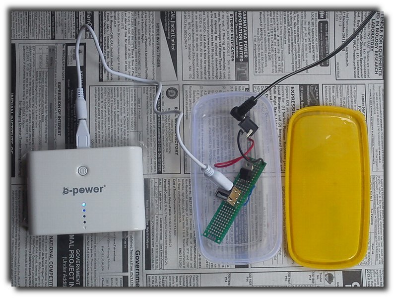
The solar panel is connected to my voltage regulator module. The 7v from the panel is dropped to 5v and supplied to the power bank. The power bank does not work with ordinary USB cables. It requires the cable+mini USB attachment that came with the package.
UPDATE (22 December 2013): I added a 1n4007 diode to prevent current flowing in the other direction when the voltage coming in from the solar panel falls down drastically. The power bank may already have the diode but I am not sure. Whether this diode would be appropriate is also something I don’t know. It is a diode and I used it. When I connect a 3.7v phone battery at the USB end, I can still measure 0.1v at the DC plug end to which the solar panel has been connected.

A diode has been added to prevent current from flowing in the opposite direction when the voltage from the panel drops below that of the batter.
How to wire a USB male port ? How to solder a USB male plug?
This photo explains it all. If the direction in which you plug it in is away from you, then the pins are positive (VCC 5+V), Data-, Data+, and negative (ground).
The red wire (by tradition) is positive. It connects to the left-most pin. The negative or the ground (black) wire goes to the last pin. I did not use data pins as my project deals only with voltage, not data.
If you get this right, then you can figure our how an USB female port is connected. If the direction in which the female USB accepts the male USB plug is towards you then, the left-most pin is ground (negative) and the right-most or last pin is positive.

How to wire a male USB port
Mini Boombox Media Player With LM386-Powered Speakers
I got this car radio replacement module mp3 media player but it did not come with a car. So, I used a pull box to provide housing for the mp3 player. The result is a Mini Boombox MP3 Player and FM Radio. The speakers are powered by a single mono LM386 IC 20x-gain amplifier minimal circuit.

My mini boombox mp3 media player.
Top-Firing Speakers

With speakers at the top, the sound easily fills the room. You can safely keep the boombox next to you but your face will not be buffeted by the sound.
I have a modded phone charger with a 2.1mm DC plug but I also created a USB-to-DC cable to power the boombox from a PC USB port. The module is rated at 12 volts but it can boot up at 5v from a USB port.

An USB to DC cable.
I can also power the boombox with a 9v battery. For that, I have created a modded battery clip with a you-guessed-it 2.1mm DC plug.

A 9-volt battery can make the boombox truly portable.
The boombox can play MP3s from SD cards, pen drives or any storage device with a USB port. It also plays FM radio. (I fashioned an aerial out of the antenna of an old RC toy remote.) The mp3 module had a line input connector and I added a 3.5 mm stereo plug for plugging in an external audio source such as a phone or a tablet.
Verdict
The speaker parts that I had used are not the best or the loudest that I have. I had to settle for smaller ones that would fit inside the pull box. Still, they are quite loud. (If I had used a cap on pins 1 and 8 of the LM386 IC, I would have had 200x gain!) The MP3 player module provides very good pre-amplified sound and I did not want do meddle with with it. The car radio module cost me around 500; the pull box was 70 and rest of the parts (accessories not included) should have been less than 100.
UPDATE 1 (20-October-2013)
Front Panel Stereo Input/Output Connectors
I went to Chennai and got 3.5mm stereo panel jack connectors. I added two of them – one for audio input and another for output. I also added a switch so that the speakers are silent when the amplified signal is sent out.

By adding stereo jacks for audio input and outout, I can now send in sound output from other media players to the boombox or send out the media player’s sound output to external speakers or headphones.
UPDATE 2 (23 October 2013)
Powered Microphone
Now that I have a line input, I decide to create a powered mike with an electret microphone.

The amplifier provides only 20x gain. It seems to be too late to add 200x gain with a 10uF cap between 1 and 8 pins of the LM386 IC.
When combined with my 200x-gain LM386 speaker-in-a-box, the microphone becomes extra sensitive and can be held at a foot or two away for regular use.

A short cable between the microphone and the speaker will create a feedback loop. I use a longer cable as the speaker-in-a-box has 200x gain.
My 200x LM386-powered Speaker-In-A-Box is a go
I had made an LM386-based amplified speaker before. The sound quality was atrocious and I switched to the silky smooth PAM8403.
PAM8403-based amplfier boards had a limitation – 5 volts. No more or else the chip burns.
The LM386 has no such limitation. In fact, its sound output of an LM386 IC is directly proportional to the voltage supplied. It can be used to power very big speakers. So, I went back to that IC.

My LM386-powered speaker can take power input from any ordinary cell phone battery, thanks to a special 2.1-mm DC plug. For AC power source, I have modded a Motorala charger with a durable 2.1mm DC plug, instead of the usual mini-USB port.
I ruined a few PCB boards before I realized that the solder by themselves will not form perfect connections on the back of the boards. The correct way is apparently to make connections using single-strand wire or the wires that form the body of resistors and capacitors.
My implementation is a text-book or datasheet version of 200x gain audio amplifier. Apart from that, I added a ceramic capacitor to eliminate noise from AC power sources and also a LED over the power input.
However, there is still noise from the audio signal input if a sound source is NOT connected. This happens only when power is flowing in. It is totally eliminated once I connect a sound source. Adding a ceramic capacitor eliminates the noise when power is flowing in but it introduces new noise when sound is flowing it. I think I need to introduce the capacitor on pins 3 and 4, instead of shorting it over the stereo input. I will do that later.
I also got a good box from the stationery section of a departmental store. I cut a square hole at the top and attached the speaker below it. The open hole is covered with umbrella cloth. I could not seal the hole from below because most glues do not form a perfect bond with the plastic material with which this box is made from.
Finally, my LM386 speaker sounds loud, suffers no noise, looks good, and is very compact and portable.
