
Tagged: electronics
3-LED flip-flop circuit
I made this circuit sometime back and I am still unsure of how it works. I saw a 2-LED version from Talking Electronics and tried this 3-LED version. All the explanations I found online are confusing. Apparently, one of the capacitors drains charge from its side of the circuit and switches off its transistor. The resistor connected to it ensures that it accumulates charge slowly. While this happens, it turns on the transistor on another side of the circuit. When that transistor turns on, the its LED lights up. When the first capacitor is fully charged, it stops supplying charge to this transistor and its LED turns off. By this time, its capacitor is accumulating charge and turning on another transistor and the LED connected to it turns on. This repeats one after another. At least, that is my understanding. It could be wrong. The flip-flop delay is controlled by the capacitor and resistor values. The voltage supplied to the circuit should be just enough to light up one LED.
Electronic Dice circuit using Arduino Uno
A re-creation of a e-Dice found in a children’s book
Some years ago, I went to a book exhibition where they literally sold imported books by the kilo. I am not speaking metaphorically. They sold books by weight. One of the books I bought was a children’s book. It had a circle-shaped plastic electronic toy stuck to the cover. It was an electronic dice. It cut through all pages and you could play a different board game on each of the pages in the book using the dice.
The dice construction was simple. Several LEDs were placed in a circle. When you pressed the center button, the LEDs lit up one after another along the circle. The dice also had a clear-plastic membrane speaker. The whole thing was powered using button-cell batteries. I saved the speaker and threw the dice away after the batteries ran out.
Silly me! I was then only interested in speaker circuits. Now that I am learning to play with Uno, I decided to re-create the dice. I have a ATtiny85 chip with which I will make this a self-contained toy. The ATtiny85 has 6 pins to connect the LEDs (I will hack the reset pin) and that leaves nothing for the speaker. I gave it a direct connection to power.
The circuit is simple. Connect the positive leads of the LEDs to the digital out pins marked for analog use (~). Connect the negative leads to a 220-ohm resistor. Connect the other end of the resistor to the ground pin on the Arduino. Connect the speaker parallel to the resistor. Add a 1uF capacitor to speaker terminals if the sound is weak.
Almost all dice circuits online are dumb. Not this one. It has sound and will be fun for kids to play with. I will order a circle-shaped sticker with numbers so that the dice is fully functional like the original toy.
Cheap DIY solar-powered home lighting system with PWM charge controller, 12-volt battery & LED strips
Costs less than ₹6000

40 watt solar panel – ₹2000
PWM charge controller (5amps) – ₹300
12v 26A battery – ₹3000
LED Strips – ₹25 to 50 per meter
Switching board – DIY
The wiring is simple. You bring a two-wire cable from the solar panel to the PWM & connect it to terminals marked Panel. Similarly, connect a two-wire cable between your 12v lead-acid battery and PWM terminals marked Battery. The Load terminals are connected to the LED switching board. The LED strips are placed in various rooms and connected to the switching board using 2-wire cables.

The PWM charges the battery when the Panel voltage is above 12 volts. It also cuts off supply to Load terminals if it draws too much current or if battery voltage falls below 12 volts.
I let the 26-amps SMF battery charge during the day and leave the LED lights on for the entire night. The LED switch board has its own always-on LED as an indicator. Initially, I had a 7 amps UPS battery. It provided lighting only for a few hours.
I put some plastic cover on them to protect from rain water. Otherwise, it is maintenance free.
On the solar panel terminals, I soldered a diode in reverse polarity to protect the panel from any wiring mistake. The PWM would have its own reverse polarity diodes I suppose.
My DIY 2.1 Subwoofer Speaker Sound System with MP3 player & FM Radio

Four years ago, I bought an amplifier board online. The seller said its output was 70 watts and it would require a 3 amps 12-0-12 volts transformer. I did not know much speaker wattage and never built the amp.
Recently, I bought the biggest subwoofer (8-inch) I could get. A carpenter built the speaker box as per my drawings. I had two 3-inch full-range Philips speakers, which I used as satellites.
My original design was much more complicated but it was a lot of work and I simplified it with minimum parts. Still it has an MP3 media player, volume controls (also on the remote), FM radio, and two 5-volt dispensing USB ports (for, say, a Bluetooth reciever). I also added a jack input hanging outside from a hole (that also acts as the pressure vent) to reduce strain on the media player.
Later, I found the amplification was provided by TDA1544q IC. This is a car amplifier providing a total of 44 watts of power over two or four channels. The board uses two channels for the satellites and other two are bridged for the subwoofer.

The orientation of the pots is flimsy as they are separate from the amp board. The front panel is too thick. Currently, they are hanging from a piece of plastic.
This was the first time I worked with AC. I got a AC-compatible flip switch.
The amp was considerably compromised by me twice when I connected the amps to it in the wrong way. The caps exploded. I replaced them. With sloppy soldering, I damaged the volume control pins when I bought it. Once I connected the sound the wrong way and the subwoofer and one satellite became silent. It drove me mad before I figured it out.

I could not get veneer and decided to paint. Nobody had pink-color paint for wood surfaces. I got that from an auto paint store. Unfortunately, it went too dark. Now, it looks psychelic dark pink.
An easy “Joule Thief” inverter circuit to power an electric torch with two LEDs using only one 1.2 or 1.5 volt (dead) battery

My handmade torch with a Joule Thief inverter design. The missing piece of the ferrite core can be found at the top of the battery. That’s the coil. The rubber band is used to hold down a momentary switch on the plastic tubing so that this photo could be taken.
These days, electric torches (flashlights) use LED bulbs. An LED bulb typically requires a minimum 1.85 volts to power on. Usually, a battery of two 1.5 volt cells (providing 3 volts) is used in torches to power them. If the voltage supplied by the cells in the battery falls below 1.85 volts, the LED will not light up. The “dead” cells in the battery will have to be replaced even though they still have considerable energy in them.
A “Joule thief” can be used to power an LED bulb using just one 1.5 (non-rechargeable) or 1.2 (rechargeable) cell. A “Joule thief” is so named because it can use just one cell. It can also power an LED with a cell that is deemed dead. The Joule thief circuit accomplishes this by using a coil to store energy and then generating spikes of voltages to turn the LED on and off several times a second. For human eyes, the LED appears to be lit up.

A Fritzing version of a Joule thief circuit
There are many videos on the Internet on how to build one. There are a number of misleading ideas of what is required to make it work. No need a circular ferrite core. I used a broken piece of ferrite core piece from a transformer salvaged from a failed phone charger. The number of windings on the coil does not increase the voltage. Instead, it affects the frequency of the voltage spikes. The voltage output is determined by the base voltage supplied by the battery and saturation level of the ferrite core. The windings need not be evenly spaced or anything like that. However, they need to be close to the ferrite core.
Parts required:
- Two white LEDs
- One non-polarized 0.1 uF capacitor
- NPN transistor
- 220 ohm resistor
- jumper wire
- ferrite core piece
- winding (enameled) wire or any insulated wire
Construction:
- Take two strands of equal-length enameled wire and wind it around a piece of ferrite core, say 20 to 40 times. Remove the enamel from the four ends of the coil. Twist/solder two ends of different wires. Use a multimeter continuity test to ensure that you are not tying the ends of the same wire. You can also use a LED+button cell combo to do the continuity test. Connect this tied end to the battery’s positive terminal.
- Now, you have two ends of coil that are free. Connect one end to a resistor and the other end to the collector of the transistor.
- Connect the other end of the resistor to the base of the transistor.
- Connect the LEDs and capacitor parallel to the emitter and collector of the transistor. The emitter is on the negative side.
- Connect the negative lead from the emitter of the transistor to the negative terminal of the cell.

Sound-activated LED lights using NPN transistor
What is wrong with the multi-colored LED light? Is it real?

I have started experimenting with transistors. The amplified AC sound signal forked from the speaker (connected to the base) is enough to turn the transistor on. The supply voltage is connected to the LED onwards to the collector and a resistor is connected to emitter (connected to ground).
I had some strange clear transparent LEDs. They turned on when on of the signal was connected to the collector but they did not react to the speaker signal. Stragely, one of the LEDs started glowing in all sorts of colors.
UPDATE: The clear LEDs are RGB LEDs. They follow their own (color) switching rhythm and are unsuitable for being sound-reactive.
Solar Panel-Powered Phone-Battery Power Bank with LM7805 USB Voltage Regulator
I wanted a phone battery power bank with a built-in solar panel. This would not have worked, as my house does not get direct sunlight. However, I have a 7v solar panel that came with a BPL emergency light. I put the solar panel on the terrace and brought its wire down to the balcony.
I could not simply connect solar panel to a power bank, as most power banks work at 5 volts. So, I built a voltage regulator module using a LM7805 IC. This dropped the voltage down from 7v to 5v. The circuit is simple. Connect the solar panel to a 2.0 mm DC power socket. Connect the two leads of the socket to the first two legs of the voltage regulator. The first leg is connected to the positive of the socket. The second and middle leg is the ground, which is shared with the output. The middle and third legs are connected to the ground and positive of the USB port.
I only had a dual-USB connector and used it anyway. This was not a bad choice. The extra surface area give its legs better anchorage. The power bank is supposedly 20,000 mAH. After I took it out of the package, I was able to charge a BlackBerry Book and one-thirds of a Micromax FunBook, both of which require 3 or 3.5 hours of charging. Now, it is charging. I have only a couple of hours of sunlight today.
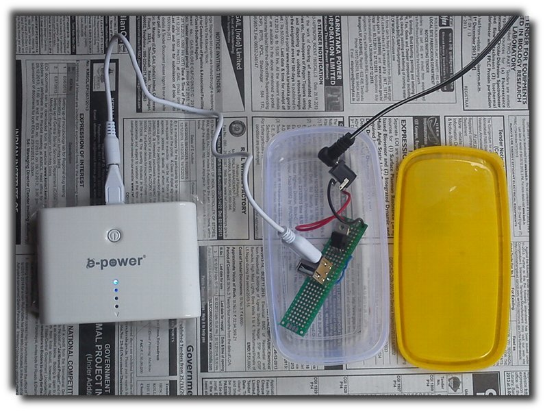
The solar panel is connected to my voltage regulator module. The 7v from the panel is dropped to 5v and supplied to the power bank. The power bank does not work with ordinary USB cables. It requires the cable+mini USB attachment that came with the package.
UPDATE (22 December 2013): I added a 1n4007 diode to prevent current flowing in the other direction when the voltage coming in from the solar panel falls down drastically. The power bank may already have the diode but I am not sure. Whether this diode would be appropriate is also something I don’t know. It is a diode and I used it. When I connect a 3.7v phone battery at the USB end, I can still measure 0.1v at the DC plug end to which the solar panel has been connected.

A diode has been added to prevent current from flowing in the opposite direction when the voltage from the panel drops below that of the batter.
DIY Electronics: My DIY Tic Tac Mint Box Universal Cell Phone Battery Charger Built With TP4056 Lithium Charging Circuit
Totally eschewing the Altoids-Schmaltoids route.
I can now charge any cell phone battery without requiring its phone or its charger. I have used alligator clips to connect to the battery. The charger circuit board has a mini USB port but I decided to connect it to a female DC jack to make the gadget more durable. There are two LEDs on the TP4056 charging circuit board – “charging” and “full charge” which can be seen through the mint box.
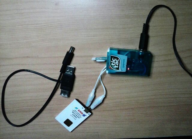
Mobile phone battery charger on a stic or rather a box of Tic Tac, powered by TP4056 IC.
