
Tagged: solar panels
Cheap DIY solar-powered home lighting system with PWM charge controller, 12-volt battery & LED strips
Costs less than ₹6000
40 watt solar panel – ₹2000
PWM charge controller (5amps) – ₹300
12v 26A battery – ₹3000
LED Strips – ₹25 to 50 per meter
Switching board – DIY
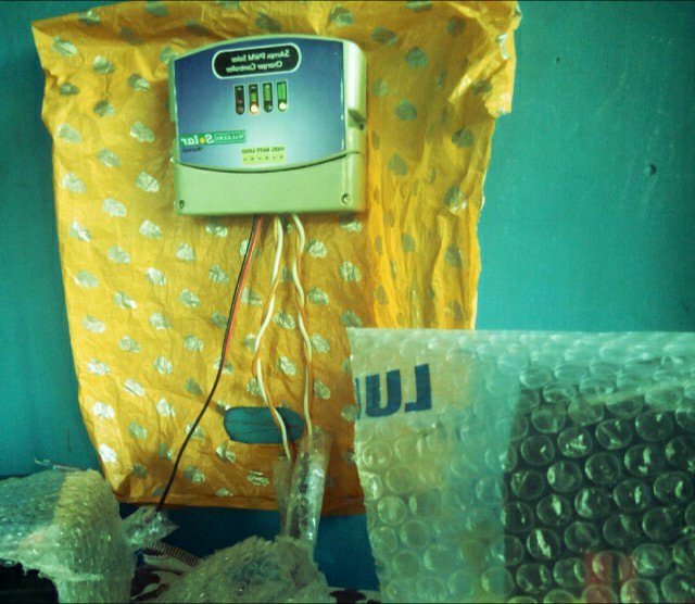
The wiring is simple. You bring a two-wire cable from the solar panel to the PWM & connect it to terminals marked Panel. Similarly, connect a two-wire cable between your 12v lead-acid battery and PWM terminals marked Battery. The Load terminals are connected to the LED switching board. The LED strips are placed in various rooms and connected to the switching board using 2-wire cables.

The PWM charges the battery when the Panel voltage is above 12 volts. It also cuts off supply to Load terminals if it draws too much current or if battery voltage falls below 12 volts.
I let the 26-amps SMF battery charge during the day and leave the LED lights on for the entire night. The LED switch board has its own always-on LED as an indicator. Initially, I had a 7 amps UPS battery. It provided lighting only for a few hours.
I put some plastic cover on them to protect from rain water. Otherwise, it is maintenance free.
On the solar panel terminals, I soldered a diode in reverse polarity to protect the panel from any wiring mistake. The PWM would have its own reverse polarity diodes I suppose.
DIY solar-powered charger for mobile phone power bank with DC-to-DC voltage converter
My earlier attempt using LM7805 voltage regulator was a success but it was not of a good design. I got another solar panel supplying voltage but the extra charge was all wasted because LM7805 dissipates heat when it drops voltage. Along with that, current is also lost.
The mobile phone power bank that I am using is rated at 20,000 mAh and takes two whole days to get fully charged from the mains. With direct sunlight available only for 6 hours, it takes 2 days of plugging in to the solar panels to get just one of the four LEDs to light up.
In this, I am using a DC-to-DC voltage converter module. This module drops the voltage while increasing the current. I have removed the LM7805 and zener diode from the charger circuit. Using the voltage converter module is a no-brainer. It has to inputs and two outputs. Inputs are connected two 2.0mm DC sockets to which the solar pannels are plugged in. The two output in the converter are connected to the USB ports.
For safe housing, I cut holes in a plastic box. Now only the USB port and the DC sockets are outside.

Solar Panel-Powered Phone-Battery Power Bank with LM7805 USB Voltage Regulator
I wanted a phone battery power bank with a built-in solar panel. This would not have worked, as my house does not get direct sunlight. However, I have a 7v solar panel that came with a BPL emergency light. I put the solar panel on the terrace and brought its wire down to the balcony.
I could not simply connect solar panel to a power bank, as most power banks work at 5 volts. So, I built a voltage regulator module using a LM7805 IC. This dropped the voltage down from 7v to 5v. The circuit is simple. Connect the solar panel to a 2.0 mm DC power socket. Connect the two leads of the socket to the first two legs of the voltage regulator. The first leg is connected to the positive of the socket. The second and middle leg is the ground, which is shared with the output. The middle and third legs are connected to the ground and positive of the USB port.
I only had a dual-USB connector and used it anyway. This was not a bad choice. The extra surface area give its legs better anchorage. The power bank is supposedly 20,000 mAH. After I took it out of the package, I was able to charge a BlackBerry Book and one-thirds of a Micromax FunBook, both of which require 3 or 3.5 hours of charging. Now, it is charging. I have only a couple of hours of sunlight today.
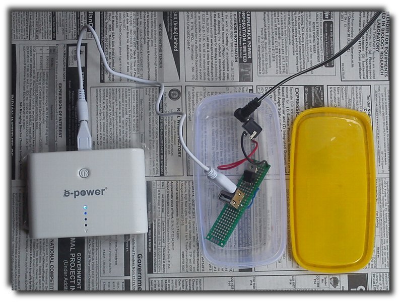
The solar panel is connected to my voltage regulator module. The 7v from the panel is dropped to 5v and supplied to the power bank. The power bank does not work with ordinary USB cables. It requires the cable+mini USB attachment that came with the package.
UPDATE (22 December 2013): I added a 1n4007 diode to prevent current flowing in the other direction when the voltage coming in from the solar panel falls down drastically. The power bank may already have the diode but I am not sure. Whether this diode would be appropriate is also something I don’t know. It is a diode and I used it. When I connect a 3.7v phone battery at the USB end, I can still measure 0.1v at the DC plug end to which the solar panel has been connected.

A diode has been added to prevent current from flowing in the opposite direction when the voltage from the panel drops below that of the batter.
